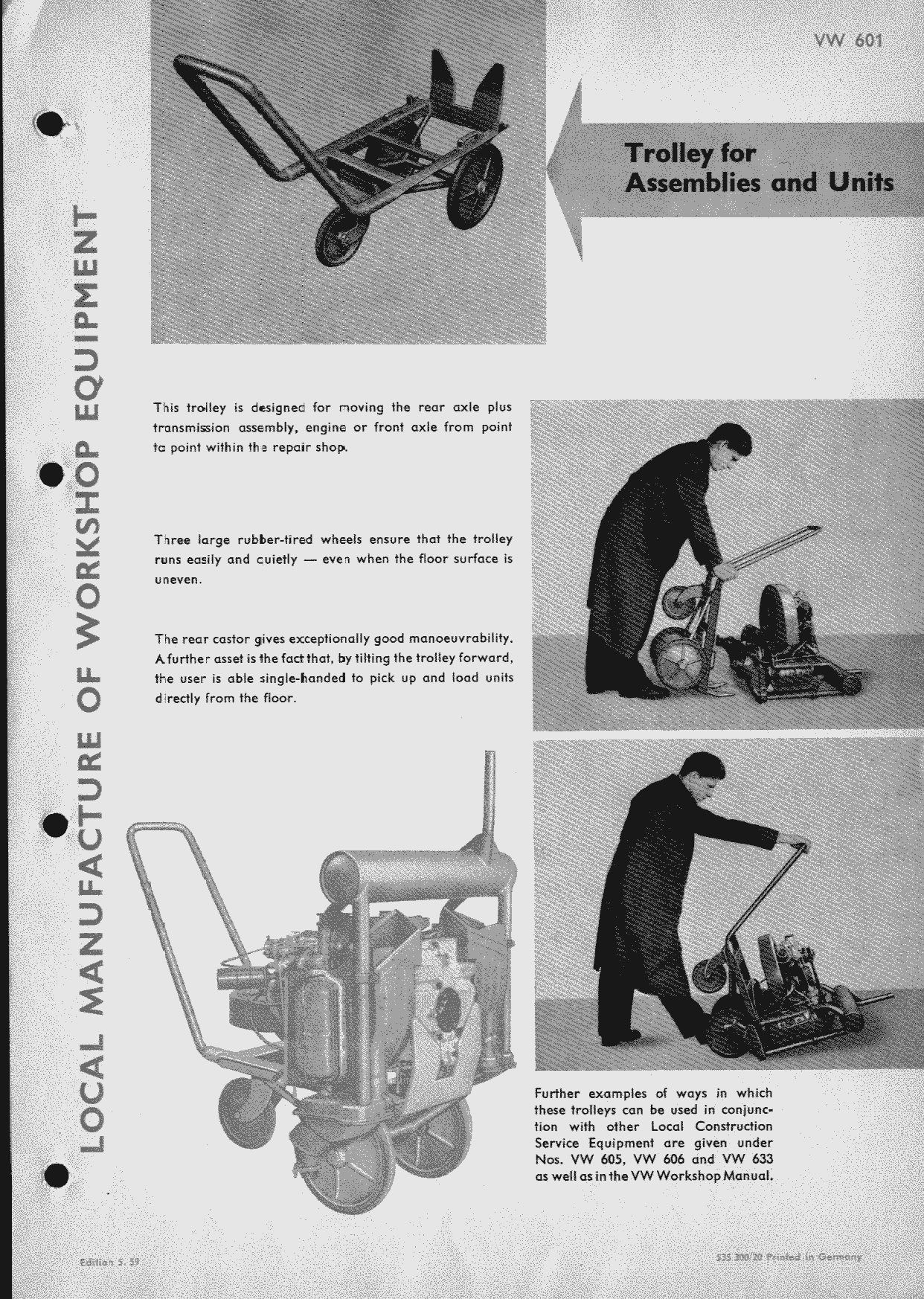
Trolley for Assemblies and Units
(Redirected from VW 601)
This trolley is designed for moving the rear axle plus transmission assembly, engine or front axle from point ta point within the repair shop.
Three large rubber-tired wheels ensure that the trolley runs easily and cuietly - even when the floor surface is uneven.
The rear castor gives exceptionally good manoeuvrability. A further asset is the fact that, by tilting the trolley forward, the user is able single-handed to pick up and load units directly from the floor.
Further examples of ways in which these trolleys can be used in conjunction with other Local Construction Service Equipment are given under Nos. VW 605, VW 606 and VW 633 as well as in the VW Workshop Manual.
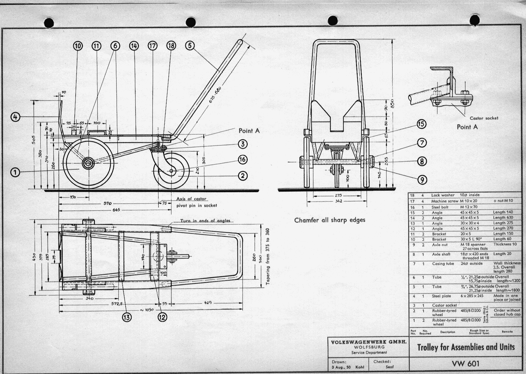
Construction Details for VW 601
- Cut off all tube, angles, strip and round bar for axle (8) to dimensions given in list of parts. Cut up tube (6), length 1200 mm (47 in.) into two lengths of 200 mm (7 ⅞ in.) each, and two lengths of 400 mm (15 ¾ in.) each.
- Bend tube (5) as shown in drawing.
- Cut a M 18 x 1.5 thread for a distance of approximately 20 mm (¾ in.) on each end of the axle (8).
- Prepare steel plate (4).
- Weld up tubes (6) and (7) and angles (12), (13), (14) and (15) as shown in the drawing.
- Weld plate (4) to front end.
- Bend up brackets (10) and (11) as shown in drawing and weld to frame.
- Roll over rear ends of angles (14) to give a good wrap round ends of tubular handle (5). Weld tube to angles.
- Insert axle (8) into axle tube (7). Fit rubber-tired wheels (1) and secure by axle nuts (9); mount wheel caps on axle threads.
- Drill four 10.5 mm (0.413 in.) holes in the welded angles (13) in positions corresponding to the holes in the castor plate and attach the latter with four machine screws (17) and lock washers (18).
- Insert rubber-tined wheel (2) into the castor fork and secure by steel bolt (16).
- Point trolley in the prevailing colour of the equipment and machines in the shop.
- Grease all bearings.


